STK Premium (Space) or STK Enterprise
You can obtain the necessary licenses for this tutorial by contacting AGI Support at support@agi.com or 1-800-924-7244.
The results of the tutorial may vary depending on the user settings and data enabled (online operations, terrain server, dynamic Earth data, etc.). It is acceptable to have different results.
Capabilities covered
This lesson covers the following capabilities of the Ansys Systems Tool Kit® (STK®) digital mission engineering software:
- STK Pro
- Communications
- STK SatPro
Problem statement
Engineers and operators require a quick way to evaluate sources of radio frequency (RF) interference. You are planning on launching a new communications satellite, which will communicate with a receiver at a ground site, into a geostationary orbit (GEO). You are concerned that a large-scale constellation of communications satellites in low Earth orbit (LEO), which transmit on similar frequencies as your satellite, will interfere with your communications link. You need to determine if interference will take place, and to what extent.
Solution
Use the Communications capability to model the transmitter on your communications satellite in GEO and the ground site's receiver. Then, use the SatPro capability's Walker tool to create Satellite Collection object to model the constellation of LEO satellites and their transmitters. Finally, use a Comm System object to bring all the pieces together to model the communications link between the GEO satellite and the ground site receiver to determine if the LEO transmitters will cause interference.
What you will learn
Upon completion of this tutorial, you will have a basic understanding of the following:
- How use a Satellite Collection object in communication analysis
- How to set up a Comm System to model interference sources
- How to determine the impact of interference sources on a communications link
Creating a new scenario
First, create a new scenario, then build from there.
- Launch the STK application (
 ).
). - Click
 Create a Scenario in the Welcome to STK dialog box.
 - Enter the following in the STK: New Scenario Wizard:
- Click when you finish.
- Click Save (
 ) when the scenario loads.
 - Verify the scenario name and location when the Save As dialog box opens.
- Click .
| Option | Value |
|---|---|
| Name | RF_Interference_Analysis |
| Location | Default |
| Start | Default |
| Stop | Default |
A folder with the same name as your scenario is created for you.
Save (![]() ) often during this lesson!
) often during this lesson!
Disabling streaming terrain
By default, the STK application connects to the Ansys Geospatial Data Cloud to distribute Earth terrain data for analysis and visualization. Turn off
- Right-click on RF_Interference_Analysis () in the Object Browser.
- Select Properties (
 ) in the shortcut menu.
 - Select the Basic - Terrain page when the Properties Browser opens.
- Clear the Use terrain server for analysis check box in the Terrain Server panel.
- Click to confirm your change and to close the Properties Browser.
Inserting the communications satellite
Use the
- Bring the Insert STK Objects tool (
 ) to the front.
 - Select Satellite (
 ) in the Insert STK Objects tool.
 - Select the Orbit Wizard (
 ) method.
 - Click .
- Open the Type drop-down list when the Orbit Wizard opens.
- Select Orbit Designer.
- Enter Comm_Sat in the Satellite Name field.
- Enter the following in the Orbital Elements panel:
- Click to propagate Comm_Sat () and to close the Obrit Wizard.
| Option | Value |
|---|---|
| Semimajor Axis | 42164 km |
| Eccentricity | 0.0027 |
| Inclination | 9 deg |
| Argument of Perigee | 302.5 deg |
| RAAN | 61 deg |
| True Anomaly | 33 deg |
Modeling the communications satellite's transmitter
Use the Communications capability to model your communications satellite's on-board transmitter.
Attaching the transmitter to the satellite
Attach a
- Bring the Insert STK Objects tool () to the front.
- Insert a Transmitter (
 ) object using the Insert Default () method.
 - Select Comm_Sat () when the Select Object dialog box opens.
- Click to confirm your selection and to close the Select Object dialog box.
- Right-click on Transmitter1 () in the Object Browser.
- Select Rename in the shortcut menu.
- Rename Transmitter1 () CommSat_Tx.
Using a Medium Transmitter model
Only some of the transmitter's specifications need be defined, so use a Medium Transmitter model for your analysis. A
- Open CommSat_Tx's () Properties ().
- Select the Basic - Definition page when the Properties Browser opens.
- Click the Transmitter Model Component Selector (
 ).
). - Select Medium Transmitter Model (
 ) in the Transmitter Models list when the Select Component dialog box opens.
 - Click to confirm your selection and to close the Select Component dialog box.
Updating the transmitter's model specs
Use the Model Specs tab to specify the transmitter's parameters.
- Select the Model Specs tab.
- Enter 1.5 GHz in the Frequency field.
- Enter 10 dB in the Gain field.
- Click to confirm your changes and to close the Properties Browser.
Inserting the ground site
The ground site is located at Offutt Air Force Base (AFB) near Omaha, Nebraska, in the Unites States.
Inserting a facility from the Standard Object Database
The facility is a hub for satellite communications. You can
- Bring the Insert STK Objects tool () to the front.
- Insert a Facility (
 ) object using the From Standard Object Database (
 ) method.
 - Clear the Data Sources - Online check-box when the Search Standard Object Data dialog box opens.
- Enter Offutt in the Name field.
- Click .
- Select Offutt AFB SATCOM Terminal in the Results list.
- Click .
- Click to close the Search Standard Object Data dialog box.
You want to search the Local Database.
Changing Offutt AFB SATCOM Terminal's altitude
The Facility object is imported with a default altitude reference. Place the Offutt AFB SATCOM Terminal on the surface of the WGS84 ellipsoid by updating its
- Open Offutt_AFB_SATCOM_Terminal's () Properties ().
- Select the Basic - Position page when the Properties Browser opens.
- Select the Use terrain data check box in the Position panel.
- Click to confirm your change and to close the Properties Browser.
Modeling the SATCOM terminal's servo motor
For this scenario, the SATCOM terminal at Offutt AFB uses a steerable antenna for its receiver. Use a targeted sensor to model the servo motor.
Attaching a Sensor object to the facility
Attach a
- Bring the Insert STK Objects tool () to the front.
- Insert a Sensor (
 ) object using the Insert Default () method.
 - Select Offutt_AFB_SATCOM_Terminal () when the Select Object dialog box opens.
- Click to confirm your selection and to close the Select Object dialog box.
- Rename Sensor1 () Servo_Motor.
Setting the sensor's cone half angle
Use a Simple Conic sensor type. A
- Open Servo_Motor's () Properties ().
- Select the Basic - Definition page when the Properties Browser opens.
- Enter 2 deg in the Cone Half Angle field in the Simple Conic panel.
- Click to confirm your change and to keep the Properties Browser open.
You are updating the cone half angle for situational awareness only; it is not required analytically.
Raising the servo motor's altitude
The sensor's
- Select the Basic - Location page.
- Open the Location Type drop-down list.
- Select Fixed.
- Enter -10 ft in the Z field in the Fixed Location panel.
- Click to confirm your changes and to keep the Properties Browser open.
Since the parent object's positive Z body points to the center of the Earth, in order to raise the sensor above the ground, you need to use a negative value for Z.
Targeting the communications satellite
The sensor's
- Select the Basic - Pointing page.
- Open the Pointing Type drop-down list.
- Select Targeted.
- Leave the Track Mode set to Receive in the Targeted panel.
- Select Comm_Sat () in the Available Targets list.
- Move (
 ) Comm_Sat () to the Assigned Targets list.
 - Click to confirm your changes and to close the Properties Browser.
The Track Mode specifies how you want to orient the antenna. By default, this is set to Receive; this orients the antenna slightly "behind" the current location of the other object. The STK application computes the appropriate amount by which to lead or trail based on the light time delay. Access computations including the computation of targeting times are performed based on the sensor being the receiver of the signal.
Modeling the SATCOM terminal's receiver
Now, model the receiver at the SATCOM terminal.
Attaching a receiver to the ground site's servo motor
The servo motor will point the receiver's antenna. Attach a
- Bring the Insert STK Objects tool () to the front.
- Insert a Receiver (
 ) object using the Insert Default () method.
 - Select Servo_Motor () when the Select Object dialog box opens.
- Click to confirm your selection and to close the Select Object dialog box.
- Rename Receiver1 () Satcom_Rx.
Using a Complex Receiver model
A
- Open Satcom_Rx's () Properties ().
- Select the Basic - Definition page when the Properties Browser opens.
- Click the Receiver Model Component Selector ().
- Select Complex Receiver Model () in the Receiver Models list when the Select Component dialog box opens.
- Click to confirm your selection and to close the Select Component dialog box.
- Click to confirm your selection and to keep the Properties Browser open.
Using a Gaussian antenna model
The
- Select the Antenna tab.
- Enter 1.5 GHz in the Design Frequency field.
- Enter 3 m in the Diameter field.
- Click to confirm your changes and to close the Properties Browser.
Creating a simple link budget
Create a simple link budget to calculate the bit error rate (BER), which reflects of how often errors occur in the transmission of digital data. You can compute a simple link budget using the
- Right-click on Satcom_Rx () in the Object Browser.
- Select Access... (
 ) in the shortcut menu.
 - Expand (
 ) Comm_Sat () in the Associated Objects list when the Access Tool opens.
 - Select CommSat_Tx ().
- Click
 .
. - Click in the Reports panel.
- Scroll to the right to locate the BER column when the report opens.
- Close the Link Budget report and the Access tool when you are finished.
Your bit error rate values look good. They are well below your 1.000000e-10 threshold.
Modeling the interfering constellation with a Satellite Collection object and the Walker tool
A
Creating the seed satellite
The
- Insert a Satellite object () using the Orbit Wizard () method.
- Leave Circular as the Type when the Orbit Wizard opens.
- Enter LEO_Sat in the Satellite Name field.
- Enter the following orbital elements in the Definition panel:
- Click to propagate LEO_Sat () and to close the Orbit Wizard.
| Option | Value |
|---|---|
| Inclination | 45 deg |
| Altitude | 2000 km |
| RAAN | 0 deg |
Reusing the Transmitter object for the satellite constellation
If the seed satellite has attached objects, such as transmitters or receivers, the Walker tool creates the same attached object for each of the child satellites. So, if you want a grouping of all transmitters in the satellite collection, create them on the seed satellite and the Walker tool will copy them onto the child satellites in the collection. You can then use these children, grouped in their own subset, in analysis tools. Since the transmitters in the LEO satellite constellation have the same properties as the transmitter on your communications satellite, you can reuse the existing transmitter for the seed satellite. This is a quick way to create a new object having identical properties to an object already existing in the scenario.
- Select CommSat_Tx () in the Object Browser.
- Click Copy (
 ) on the Object Browser toolbar.
 - Select LEO_Sat () in the Object Browser.
- Click Paste (
 ) on the Object Browser toolbar.
 - Rename CommSat_Tx1 () LEO_Tx.
Creating a new Satellite Collection object
Insert a new Satellite Collection object into your scenario.
- Bring the Insert STK Objects tool () to the front.
- Insert a Satellite Collection object (
 ) using the Walker Tool () method.
Using the Walker tool
Use the Walker tool to
- Click Seed Satellite: when the Walker tool opens.
- Select LEO_Sat () when the Select Object dialog box opens.
- Click to confirm your selection and to close the Select Object dialog box.
- Leave the Pattern Type set to Delta in the Shell properties panel.
- Set the following parameters for the satellite collection:
- Enter LEO_Sats in the Name field in the Container Options panel.
- Click to propagate the LEO_Sats () Satellite Collection object.
- Click to close the Walker tool.
- Clear the check box for LEO_Sat () in the Object Browser.
In a Delta pattern, the orbit planes are evenly distributed over 360 degrees around the central body.
| Option | Value |
|---|---|
| Number of Sats per Plane | 10 |
| Number of Planes | 10 |
| Inter Plane Phase Increment | 1 |
You do not need to visualize it for this analysis.
The Walker tool automatically generates a satellite collection subset for each plane and two additional subsets, one of which includes all the satellites and another which includes all their transmitters.
Modeling interference with a Comm System
The Communications capability includes Comm Systems, which allow you to model dynamically configured communications links between constellations of transmitters and receivers.
Adding the Comm System object to the Insert STK Objects tool
To build a Comm System, you must first add the
- Bring the Insert STK Objects () tool to the front.
- Click .
- Ensure the New Object page is selected when the Preferences dialog box opens.
- Select the Show check box for Comm System in the Define Default Creation Methods panel.
- Click to confirm your selection and to close the Preferences dialog box.
Inserting a Comm System object
Insert a new Comm System object into your scenario.
- Insert a Comm System (
 ) object using the Insert Default () method.
 - Rename CommSystem1 () CommSystem.
Creating the transmit constellation for the Comm System object
Identifying components of the Comm System consists of organizing groups of transmitters, receivers, and radars into constellations,
- Bring the Insert STK Objects () tool to the front.
- Insert a Constellation (
 ) object using the Define Properties () method.
 - Select CommSat_Tx () in the Available Objects list when the Properties Browser opens.
- Move () CommSat_Tx () to the Assigned Objects list.
- Click to confirm your selection and to close the Properties Browser.
- Rename Constellation1 () Tx.
Creating the receive constellation for the Comm System object
Now, create the constellation to carry out the receive function.
- Insert a Constellation () object using the Define Properties () method.
- Select Satcom_Rx () in the Available Objects list when the Properties Browser opens.
- Move () Satcom_Rx () to the Assigned Objects list.
- Click to confirm your selection and to close the Properties Browser.
- Rename Constellation2 () Rx.
Because you have already used the LEO_Tx Transmitter object as part of your Satellite Collection object, you do not need to create a separate constellation for the interference sources.
Selecting the Comm System transmit and receive functions
Use the Comm System object's Basic properties pages to select constellations to carry out the transmit and receive functions in the Comm System.
- Open CommSystem's () Properties ().
- Select the Basic - Transmit page when the Properties Browser opens.
- Select Tx () in the Available Constellations list.
- Move () Tx () to the Assigned Constellations list.
- Select the Basic - Receive page.
- Select Rx () in the Available Constellations list.
- Move () Tx () to the Assigned Constellations list.
Selecting the Comm System's interference source
Use the Comm System object's Basic - Interference page to select one or more constellations — or in this case, satellite collection subsets — of transmitters to function as potential interference sources.
- Select the Basic - Interference page.
- Ensure that the Calculate Interference check box is selected.
- Select LEO_Sats/AllTransmitters (
 ) in the Available Constellations list.
 - Move () LEO_Sats/AllTransmitters () to the Assigned Constellations list.
- Click to confirm your changes and to close the Properties Browser.
This will
Computing the Comm System data
Now that you have defined the Comm System,
- Select CommSystem () in the Object Browser.
- Select the CommSystem menu in the Menu Bar.
- Select Compute Data in the CommSystem menu.
When you select Compute Data, a two-phase process begins to generate the desired information. The first phase analyzes the visibility of the transmitters, receivers, and interferers to each other to determine when they are accessible. Access calculations take into account any of the normal access constraints that may be applied to each of the objects. The second phase steps through the desired Comm System interval, calculating the link performance. The first phase of calculations is completed rather quickly but the second phase can be lengthy, depending on the complexity of the Comm System. You can follow the progress in the Status Bar at the bottom of the STK workspace.
Viewing the Comm System in the 2D and 3D Graphics window
After link performance and interference are calculated, the desired links, interference sources, and the primary interferer are shown in the 2D and 3D Graphics windows.
- Note the locations of Offutt_AFB_SATCOM_Terminal, Comm_Sat, and the markers of the satellites in the Satellite Collection in the 2D and 3D Graphics windows.
- Note the access lines; the primary interferer is marked with a red line and the primary link with a green line.
- Click Start (
 ) on the Animation toolbar.
 - Watch as the primary interferer changes as the satellites in the Satellite Collection move over time.
- Click Reset (
 ) when you are finished.
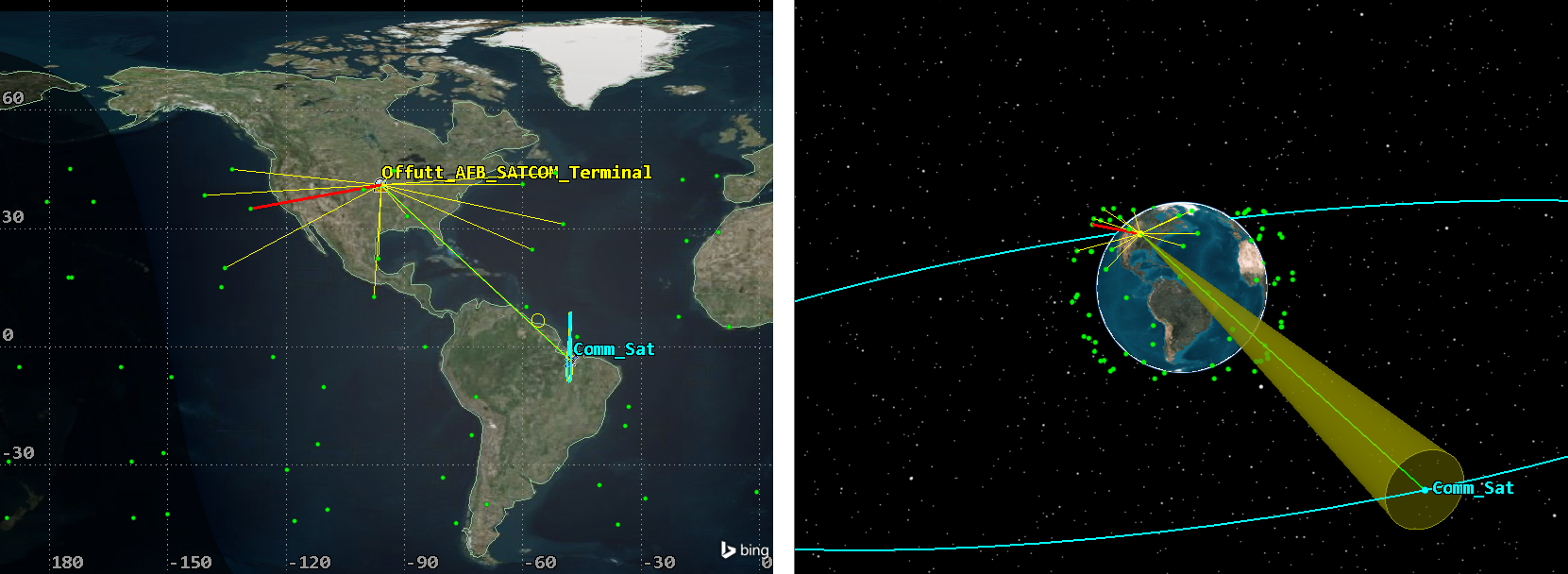
Comm System Graphics
Your views will be different than those shown in the image above.
Evaluating interference with a custom report
With your interference sources factored in to your communications link via the Comm System object, build a custom report to evaluate the effects of the interference.
Creating a new report style
You can easily create a
- Right-click on CommSystem () in the Object Browser.
- Select Report & Graph Manager... (
 ) in the shortcut menu.
 - Select the My Styles (
 ) folder in the Styles panel when the Report & Graph Manager opens.
 - Click Create new report style (
 ) on the Styles toolbar.
 - Enter BER Interference to rename the new report style.
- Select the Enter key to open BER Interference's Properties ().
Selecting the Link Information data provider elements
When the report properties open, you need to choose the data providers and required elements for your analysis. The
- Select the Content page when the Properties Browser opens.
- Expand () the Link Information () data provider in the Data Providers list.
- Move () the following data provider elements to the Report Contents list in the order shown:
- Time (
 )
) - BER ()
- BER+I ()
BER+I is the Bit error rate in the presence of interference.
Updating the BER notation
Both the BER and BER+I notations default to a Floating Point, but you want to use Scientific notation. You can update the notation by adjusting the
- Select Link Information-BER in the Report Contents list.
- Click .
- Open the Notation drop-down list in the Data Format panel when the Options: Section 1, Line 1, Link Information-BER dialog box opens.
- Select Scientific (e).
- Click to confirm your change and to close the Options: Section 1, Line 1, Link Information-BER dialog box.
Updating the BER+I notation
Update the BER+I notation to match.
- Select Link Information-BER+I in the Report Contents list.
- Click .
- Open the Notation drop-down list in the Data Format panel when the Options: Section 1, Line 1, Link Information-BER+I dialog box opens.
- Select Scientific (e).
- Click to confirm your change and to close the Options: Section 1, Line 1, Link Information-BER+I dialog box.
- Click to confirm your changes and to close the Properties Browser.
Generating the custom report
Recall that a BER+I value greater than 1.000000e-10 indicates interference to your communications system.
- Select BER Interference in the My Styles () folder in the Styles panel.
- Click .
- Compare the BER and BER+I columns.
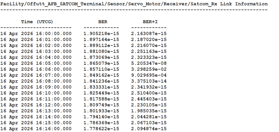
BER and BER+I Report
Viewing the primary interferer information in the 3D Graphics window
A Satellite Collection object, by default, places a marker a the location of each satellite in a subset. You can find information on a particular satellite by double-clicking on the satellite marker in the 3D Graphics window. In this case, you can use it to find information on the primary interferer.
- In the custom report, right-click on the first time a BER+I value is greater than 1.000000e-10.
- Select Time in the shortcut menu.
- Select Set Animation Time in the Time submenu.
- Bring the 3D Graphics window to the front.
- Double-click on the satellite marker at the end of the red access line to obtain information on the interference source.
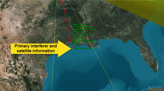
satellite interference source
Your image will be different from the above image, but similar.
Saving your work
Clean up your workspace and close out your scenario.
- Close out any open reports, tools, and the Report & Graph manager.
- Save () your work.
- Close the scenario when you are finished.
Summary
You created a link budget between your ground site and a communications satellite. The resulting data showed good communications. You used the Walker tool to create a satellite collection to model the proposed constellation of satellites that could interfere with your communications. Using a Comm System and the Report & Graph Manager, you determined that the constellation of satellites will indeed interfere with portions of your communications.
On your own
There are several methods for analyzing interference with the STK application. Using STK objects outside of a satellite collection, you can add interference sources directly within a Receiver object to assess their impact on the performance of a receiver. For more in-depth interference analysis, you can use the Spectrum Analyzer plugin to perform electromagnetic spectrum analysis on specific inference sources and to visualize frequency overlap and study methods to minimize the interference by adding RF spectrum filters and adjusting the communications settings.